Archive

Retrocomputing

Many thanks to everybody who read and commented on last week’s article. Our posting was picked up by The Register and then by Slashdot. In two days, we hosted more than five thousand readers: more footfall than we usually experience in a year.

In the article, I set out to look at what we have learned about radio interference problems and best practice as a result of legislation. Engineers find this an engaging subject, because it has transformed the way that we see the world and how we approach our work. EN55022, on which I focused, is just one of many new regulations that are increasingly affecting our trade. The ZX Spectrum neatly illustrates that we have made genuine progress, and it does so in a refreshing way.

Those who enjoy modifying and continuing the legacy of the computer (and there are many such people) may be a little let down that I didn’t do more. However, I couldn’t please everybody in the space of a blog posting, and I didn’t attempt to. What follows is a consolidation of much of the feedback we received.

EMC isn’t important

It is clear that there are two, and perhaps three, camps in the general argument about electromagnetic compatibility [EMC]. A few correspondents sincerely believe that none of it matters and, in a limited context, they’re right. In the domestic situation, you’re unlikely to encounter a compatibility problem that endangers your life or livelihood. For a lot of people, the fact that home computers would knock out radios, televisions, or toys in the vicinity just blends into part of the nostalgia.

trs80bigtrak

Collision course: the Tandy TRS-80 and MB Games Bigtrak wouldn’t share a room together (thanks to Animats on the Slashdot board for the example)

The other camp, in which I include myself, will contend that good EMC practice is of prime importance. Although I concede that the test limits are arbitrary, we have a duty to invest serious effort in designing equipment that people can use in any way they like, without it disrupting their work or leisure.

That same argument can be extended to rules like RoHS, however clumsily it was introduced, and further into educating engineers about conflict minerals, and particularly tantalum. These things force us to confront the fact that we all shape the world, and the products we design have consequences beyond our influence.

It’s not just about our consciences; it’s good business. What might have been novel and forgivable in the 1980s, when all electronic equipment tended to be a little shambolic and every user was a pioneer, is not so endearing in younger products. Customers today are more sophisticated and less forgiving about environmental and ethical issues, factory conditions, technical problems, even delays in shipping, and we have to be at least as sophisticated as they are.

There is a third camp, whose argument, succinctly, is that a few cowboys spoil everbody else’s fun. Telecommunications products, for example, still run roughshod over EMC regulations because certain products, that transmit radio as an essential part of their function, are exempt from large parts of EN55022. Today, when I plug my cordless phone into the wall, it knocks out the radio on the other side of the room. It’s the switch mode power supply that does this, because the system is exempt and it costs a few cents to buy components that quell the energy it’s emitting.

These issues remind us of the bad old days, but we should set our own sights higher. Let us imagine if every competitive advantage was justified, irrespective of the means, just because nobody had legislated otherwise. We would all be designing dreadful equipment, avoiding our taxes, destroying the world around us, and cynically manipulating and reinterpreting the rules to suit ourselves. Some people do this, but most people don’t, which is why we have lasted this long as a species.

It’s a moot point these days, though: if we don’t meet EMC requirements, we don’t have a product we can sell.

The Metal Box Scenario

screening
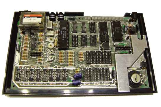
Screening: a large example of a screening can; a heat sink on the Issue 6a Spectrum that might have been a shield but wasn’t; a sprayed can in a spray can.

Many correspondents pointed to the Faraday Cage. Simply make the case out of cast metal, or coat the inside with a special paint, contrive a method whereby this can be earthed, and radio signals can no longer enter or leave. You suddenly have a compliant product. Simple, right?

It depends. If you’re retrofitting one computer, or you’re making a few dozen of a new product, it is indeed simple: you control the process, you dictate the quality of the result, and you are selling your products or services at enough of a profit that the cost of a can or two of conductive spray paint presents no difficulty. You may still have problems with your cables radiating, though.

If you’re contracting your manufacturing and knocking out tens of thousands of products, though, there are big problems with this kind of technique. Use conductive plastics or cast metal and you change the finish of your product, you accelerate the wear on your tools, and you raise material costs. Use a spray coating, and you must accept that a good proportion of your plastics will be rejected because the paint finish is unacceptable in one way or another. You create a new quality control step, and a new manufacturing process where your equipment must be coated and dried, which impacts on the production line. Aside from having to pay for the extra labour, suddenly you have to store case materials very carefully on massive racks of shelving for several hours while they dry. You’re paying for this time, this floor space, and this temporary storage.

That’s why we accept plastic cases in mass production, and design our products so that the enclosure doesn’t matter. Faraday cages still have their place in modern electronics: if you look inside a mobile phone, you’ll see them soldered to the printed circuit board to protect or defend against selected devices. We can’t enclose everything we make in metal cases, or it would price us out of certain markets entirely, so we find other ways to make our products comply.

Plus ça change

When is a Spectrum not a Spectrum? My attention has been directed towards a number of novel retrofits and research products. Some of these are worth a look:

As many correspondents point out, we can make an impact on radiated emissions if we tinker around the edges. The failure I described as ‘abject’ may be ameliorated with a few simple modifications. Perhaps it would then pass; perhaps it wouldn’t. I would have liked to try these, but unfortunately didn’t have the time.

If we allowed ourselves a more drastic redesign, we’d have a device that behaves like a Spectrum, but when would it cease to be one? If we change the RAM, so it no longer requires those extra power supplies, and then we disable them, is it still a Spectrum? If we change the 7805 regulator for something that doesn’t throw away about 60% of the input power, then remove the heat sink, is it still a Spectrum? Do these conservation projects really preserve the Sinclair legacy?

An old computer is what it is: a product of the market, engineers, and achievements that produced it. These days, a good engineer could create a passable version of this computer using off-the-shelf components and software in a couple of weeks. It’s easy to redesign in hindsight, when technology has moved on and improvements are cheap and even obvious — that’s another article. But in 1982, making a Spectrum was a different order of challenge.

There were five major modifications of the ZX Spectrum’s electronics during its production for reasons of cost, yield, and quality, and by the end they had a much better product. Most of the area on a ZX Spectrum motherboard was taken up by RAM and the electronics required to access it: something you could now do in two or three square centimetres of board space. In 1982, you couldn’t make a computer with a four-layer board economically. Today it is a trivially simple process.

Coda

The abysmal video output and the lack of memory of my current Spectrum drives me a little crazy. I’ve also forgotten how slow the BASIC is, which must be why I decided, at the age of ten, to teach myself assembly language.

While it’s tempting to take this and all my correspondence on board, be influenced by latter-day add-ons such as divIDE, and produce another almost-Spectrum in the manner intimated by my previous post and the links above, that would involve an awful lot of time that I don’t currently have. It’s expensive to make the first one properly, and I’m not certain there’ll be a market for others.

So, what am I going to do with my Issue 2 Spectrum? The next thing I intend to do is to take another look in the EMC chamber to see if the simple modifications I suggested in the last article will make it pass, as there’s a relatively low risk of messing up my computer if I stick to some fairly basic changes. I’ll get back to you in March, when the snow has melted and we’ve booked a little more time in the chamber.

For the next few postings, though, forgive me if I steer the subject back to Focusrite.

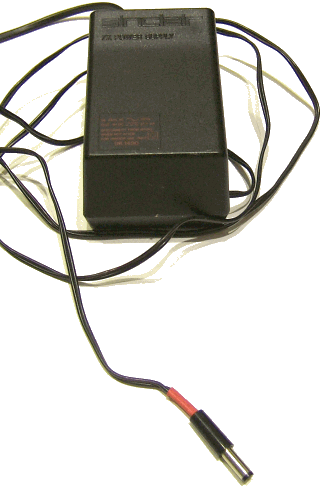
Photo credits:TRS-80 / Bigtrak / P&O container (the article is great) / Issue 6a Spectrum / Nickel spray.

Last week, I finished my article on an uncharacteristically cruel cliffhanger. Before I let the results slip, I should qualify them a little. I have already said that we’re giving this ZX Spectrum a head start, firstly by disabling the TV modulator, and then by allowing the test setup to exclude a TV, cassette recorder, and associated cabling, as would normally be required by the rules.

December’s snow handed our test subject a third advantage. Traffic accidents caused by bad weather cost us two hours in the test chamber, and we were able to take only a reduced set of readings. Six complete frequency sweeps were taken, at three angles around the equipment in horizontal and vertical polarisations, with the antenna at a height of 1.5 metres.

This is the first stage of a radiated emissions test to EN55022. The next would require us to focus on the five most problematic-looking frequencies, determine the angle, antenna height, and polarisation for which these have maximum strength, and ensure that the signal is still beneath the pass line. This accounts for the isolated red crosses on last week’s graph. Such a test would take a couple of hours for us to perform completely.

What do we already know about a ZX Spectrum’s RF performance? Anecdotally, there are a couple of causes for concern. The first is that we can actually hear the machine chirping at us when it’s switched on. Here’s a recording of it (hosted off-site), with the computer loudspeaker playing a suitably Kamikaze tune before the computer resets itself. This demonstrates how horrendously loud this chirping is, and also how it modulates during reset.

The chirping is caused by the circuitry that generates the −5V power rail for the RAM chips. It works by switching current through a transformer coil several thousand times per second.  Because we can hear this, the switching frequency is too low to cause much hassle at radio frequencies. However, it implies that corners have been cut. The transformer has been wound fairly crudely and hasn’t been potted to prevent acoustic noise, and the control circuit changes its switching frequency to compensate for the fluctuating load when the RAM starts working. In fact, the whole system is likely to be amplifying and feeding its own mechanical vibrations, generating extra nastiness. No expense spent.

A bigger concern is that, when we look at the screen, we can clearly see the chip’s clock breaking through, manifesting as vertical stripes in the background of the image. This possibly occurs in the ULA chip whose purpose is to glue the screen, memory, cassette sockets, and processor together. It’s producing a fluctuation of a few tens of millivolts on the video signal, and this doesn’t look promising for signal integrity.

Stripy Spectrum

The circuit board has two layers, and ‘plated through’ holes that selectively join them together  – an unusually exacting specification in the early Eighties, but outdated practice today for a board like this. There is no internal copper plane for the power or ground connections as there would be now, so signal current must flow and return along tracks arranged in wide loops. Large loops are bad from a radiation point of view, because they constitute resonant systems.

It doesn’t seem great so far. As any engineer who knows this computer would suspect, it doesn’t measure very well either:

ZX Spectrum EMC

Final readings could easily be 10dB or more above the peaks on this graph, so it’s not just a failure; it’s an abject one. Even that fuzz just above 100MHz might prove problematic when we connect more cables and look more closely.

One of the two most problematic frequencies, 42MHz, we could have predicted. It is the third harmonic of the main crystal. The fundamental frequency of 14MHz finds its way into all sorts of places: it’s divided by four to generate the microprocessor’s master clock (3.5MHz); it paints pixels onto the television (14MHz / 625 PAL lines / 25Hz frame rate = 896 clock cycles per line); generally it also couples into large parts of the circuitry.

The 48.8MHz peak is attributable to a different problem. When the emissions were being measured, we observed that quite a lot of the radiation was vertically polarised. Because PCB tracks and components are horizontal, electromagnetic radiation that originates from the circuit board has hardly any vertical component. Vertically-polarised energy is an indicator that the power supply cable is radiating. The Spectrum’s cable is exactly 1.5m long, which causes it to resonate fairly effectively at about (0.95 × c)/(1.5 × 4) = 48MHz. This 48.8MHz peak is an upper harmonic of the PAL colour clock (4.4336MHz × 11) that just happens to hit the resonant frequency of the power cable. If the cable were a different length, it would just pick out a different harmonic, moving the spike upwards or downwards.

A: Invalid argument

I can’t simply slaughter a piece of computing history on a rotating altar and walk away. Let us perform a proper autopsy. How and why does the Spectrum fail, and what might we do today to improve its RF performance?

It’s a hard question to answer, firstly because I don’t want to test my computer destructively to find out; secondly because we just wouldn’t design a computer in the same way today. In 1982, Sinclair Research worked miracles in compressing the functionality of a home computer into just four main chips plus RAM.

As we have seen, though, the first thing we would have to change is the rather fishy power supply and cable.

ZX Spectrum PSU

As with almost every computer power supply today, its replacement would have to have a ferrite, and both conductors would run through a hollow shield to reduce radiation. Sinclair power supplies are moulded shut and I don’t want to destroy mine, but it is likely that this single step would provide a good deal of radio attenuation: perhaps ten or twenty decibels.

Where the DC jack enters the computer, we would add a common-mode inductor and some extra inductors and capacitors to clean up the power lines. We would need similar components to protect the TV and cassette cables. However, the data lines between chips probably don’t need slewing: presciently, the ULA included the facility for building suitable resistances into the chip itself. Given the high board density, even adding these few inductors and capacitors to fix individual radiation problems would entail a non-trivial redesign and there would be no guarantee of success. There is also the problem of cost: these components would probably add a pound to the material cost of the computer. By the time the customer saw it, though, the manufacturer, distributor and store would have added their margins, resulting in a retail price increase of three or four pounds. It doesn’t sound like much, but it would have made Sinclair’s eyes water: he sold millions of these based on low retail prices and high margins.

E: Out of DATA

As an epilogue, I shall consider what we might do if we were given a cleaner slate. Firstly, what would happen if we were asked to make a Sinclair-compatible clone that could legally be sold? Those RAM chips are now museum pieces and change hands for a few pounds each. The custom ULA, manufactured by Ferranti, is technically impossible to replace because Ferranti went spectacularly bust in the 1990s. Only the Z80 microprocessor and mask ROM remain obtainable in recognisable incarnations, but economies of scale nowadays render that kind of technology abysmal value for money.

speccyinside

The cheapest and safest solution would actually be to emulate the Z80 processor in software running on a more modern chip. Inside this chip, costing maybe £2.00 or less, would be encapsulated all the ROM and RAM that the Spectrum needs to function. The parts of the ULA that drive the screen and cassette would be designed around special input and output functions that are provided by these chips, although the video generation would still require an extra device of its own.

Meanwhile, the big heatsink and 7805 regulator (surrounding the loudspeaker in the bottom-right hand corner in the photograph above) would be replaced by a modern switch-mode regulator that dissipates barely any heat at all, and all that sheet metal would go. We wouldn’t need the -5V supply any more, and we wouldn’t fit a TV modulator: modern TVs cannot demodulate an analogue signal, and VGA or component video would suffice.

Using surface-mount technology, the circuit board would be shrunk to about a fifth of its existing area, so it would resemble a narrow strip along the back that holds the rear sockets, extra components for EMC, headers for the keyboard membrane, and the familiar edge connector which, if we were expecting our device to last for another thirty years, we might consider gold-plating.

The new design would require a four-layer board for electromagnetic reasons, increasing the cost slightly.  If we were making enough of these devices, we’d be able to sell the whole thing for about fifty pounds assembled, with a printed manual – less than half of the actual cost of a Spectrum in 1982 without allowing for inflation, and about the same price as a reasonable second-hand specimen today. We may still make a modest profit.

But I’m considering emulation, and emulation is cheating. Nevertheless, it is the cheapest and quickest way to build a Spectrum today. There are other ways that purists would appreciate more – see, for example, the labour of love that is the Harlequin Project – but these require more complex chips and hence more cost. We may, as an ironic twist, use an ARM chip: these are cheap, powerful, and started life in the offices of Sinclair’s arch rivals at the time, Acorn Computers.

One troublesome question would remain: we’ve built a compatible, but what we could do with all the unused power? With the ROM now held in electronically erasable memory, we could offer operating system upgrades. We could turn the clock speed up and increase the memory practically for free, so why shouldn’t we? We might no longer limit ourselves to emulating a particular 8-bit processor, or to emulating a foreign processor at all. This would allow us to use greedier screen modes, and so provide enhanced graphics. We could change the ROM to allow ourselves to program in a more modern language, attach an SD interface to load and save games quickly and reliably, improve the sound capabilities and the tape modulation scheme, add serial ports and MIDI and USB, even imitate other computers. And so on.

The end of this train of thought always matches the beginning. We’re engineers. We love ideas, and we love experimenting with computers. Were we to reissue the Spectrum today with our vastly improved resources and a commensurately pioneering spirit, we’d create a computer that is nothing like the Spectrum. What we would end up would look more similar to a Raspberry Pi, which was conceived with a similar spirit and restrictions and followed a fairly similar path. If we insisted on affixing a keyboard and screen, it would resemble a small laptop.

More likely, though, if we wanted to be the true successors to Sinclair’s aesthetics and vision, our new device would resemble a smartphone. These shrink-wrapped products represent the leading edge of power, versatility, convenience, and style. Supported by a burgeoning industry of home-grown applications, phones rather than personal computers now excite and engage young people. Some just use them to consume, but others have discovered that phone applications can be written using free software and then distributed for free to the world. This has started to democratise computing again in the same way that Sinclair did thirty years ago.

Sir Clive now states in interviews that he doesn’t own a mobile phone. He might wrinkle his nose at the dominance of the Asian hardware consortia and giant American software companies that so swiftly ate his lunch in the Eighties. He might fear the collective infantilisation and lack of peace of a society in which everybody is glued to a telephone. But he must, surely, approve of the renaissance of home-made software.

Why can’t you really use a mobile phone in a petrol station forecourt? Why do you have to turn off digital cameras and MP3 players during take-off? The reason is that every piece of electronic equipment you will ever own has a secret life as a radio transmitter.

I’ll start explaining what happens using sound waves instead of electromagnetic ones, as they’re slower, less mysterious, and you can hear them. An organ pipe has a natural tendency to resonate. If you place a source of turbulent air at one end, it will travel to the other end. Some of it will leave the tube, but some will be reflected back: this back-propagation is a kind of shock-front caused by the travelling wave suddenly emerging into the open air. That reflection is reflected again when it reaches the first end of the pipe, and so on. A pressure wave can travel up and down a pipe for some considerable time without dissipating. The resulting periodic pressure also influences the source of air, to the extent that a really good standing wave is set up. As long as the air flow keeps it energised, it is quite stable.

So, organ pipes need three things: a source of energy, a long, thin shape to guide the sound wave along, and an end that’s open to the world to allow the sound to radiate and the shock-front to propagate back down the pipe. Electromagnetic waves in wires share many similarities to acoustic waves in the way that they propagate, and it turns out that these similarities include the propensity for resonance.

So, what does an FM radio antenna look like? It’s generally a piece of wire of a carefully-selected length, with a high-frequency signal being driven into one end, and the other end left unconnected. A signal travels up the piece of wire, and some of it travels back down the wire as a reflection. The fact that the wire is tuned by choosing its length to match the carrier frequency helps the system to resonate, and electromagnetic radiation propagates into the air.

ImageThe Hannington transmitter in Hampshire: if you squint, it’s an organ pipe.

Yes, this is a simplification: many antennae look like this; those that don’t are designed so that that they focus their radiated energy, or their coverage, in a particular direction. If we’re going to call Hannington an organ pipe, we can call the microwave mushrooms that formerly decorated the BT Tower flugelhorns. The principle is the same.

Anyway, it turns out that a resonant system is created on a printed circuit board whenever we connect two chips that exchange information: one of them produces a high-frequency signal with nice sharp transitions. It travels down a copper track with all its harmonics stretching gloriously to infinity, and into the input pin of the device that’s reading it. Usually, the input pin is designed with efficiency in mind, so that it doesn’t use much current to read the signal (a certain class of engineers will now be uncontrollably murmuring ‘high input impedance’ at the screen). The far end of the track therefore appears to be very similar to a piece of unconnected wire. The signal and its harmonics travel back down the wire and, even if the length of the track isn’t quite matched, we are suddenly transmitting a little bit of radio. This process is reciprocal, so a little current will flow in the wire in response to strong radio waves. In fact, it’s more complicated than that, because the power connection that supplies both chips behaves in a similar manner.

Why does any of this matter? Well, ordinarily it wouldn’t, until you happen across a piece of equipment that radiates a bit of energy at a certain frequency, and try and make it work at the same time as another piece of equipment that is susceptible to interference at that frequency. Suddenly you have a fault that stops them playing nicely together for mysterious, magical reasons. Neither manufacturer accepts culpability because it’s not entirely their fault and, if you’re really unlucky, the fault kills people.

Of course, we now live in a world full of radio energy, and we rely increasingly on electronic devices for our safety and security, so we are rapidly accumulating anecdotes of near-lethal situations in which electronics fail. A friend of mine managed to crash his heart pacemaker during a compliance test, and it was broken for weeks. His hospital found out during a routine check, discovering that its system clock had stopped at the time he was wandering about inside an EMC test chamber. If it doesn’t kill you, it might just cost you money. That’s why customers are required to turn off mobile phones at the petrol pumps, just in case they mess up the payment system.

So, why does any of this matter to a manufacturer of audio toys? The simple answer is legislation.

That’s the sound of the police

Since the mid-1990s, various laws have ensured that designers and manufacturers need to take electromagnetic radiation seriously. We must certify our own equipment as complying with these regulations in order to sell it, and have to produce documentation on demand to show that we have made the effort. If our products don’t comply, we will be fined. Sometimes we do the compliance testing ourselves; sometimes, when we expect compliance issues to be straightforward, our manufacturer does it for us.

CE/FCC
As well as electromagnetic tests, there are tests to see if equipment can withstand static shocks without crashing or being destroyed, to check that mains-powered equipment can withstand power surges and drop-outs, and to ensure that harmful radiation isn’t propagated down interconnecting cables into neighbouring equipment. This is all very reassuring for the consumer but, interestingly, we often find good, defensive radiofrequency design practice is at odds with the most optimal audio circuit design: particularly when so much of the audio world is still using those horrible phono cables to transmit its most sensitive signals. This leads us to invent a host of novel circuits that serve both masters, and to a ceaseless and obsessive evaluation of our best practice.

The details of what we must do are not the most exciting subject for a non-specialist, but they have shaped the world around us in a few ways. One thing you’ll have noticed is that more and more pieces of equipment tend to come with separate power supplies, rather than accepting an input directly from the mains as they used to. This allows the designers to buy in a power supply from a third party that has already been tested, and prevents them having to test their own for compliance, in accordance with the volume of extra legislation that covers mains-powered equipment.

The second thing is those ubiquitous lumps on computer power supply cables and USB leads.
USB with ferrite This is a ferrite. It’s just a doughnut of material containing mostly iron powder and resin, which magnetises slightly in response to current flowing through the cable and, in magnetising, generates its own field in opposition. That’s its only function. In doing this, it suppresses nasty electromagnetic problems below about 80MHz surprisingly well. Nobody likes them, but we put them on the cable because the CE marking criteria are very strict, and most equipment will fail by a hair’s breadth without them.

Radio silence

To give a quick indication of what we need to do, here is a picture of a bit of one of our products, with parts marked that we use only to make it pass electromagnetic legislation. If we designed the product without them, everything would work in the same way, but the unit wouldn’t get certification.

Product X

  1. A multi-layer circuit board. Most circuit boards these days have internal layers, and this is often just for electromagnetic compatibility. Multi-layer boards are built up from sandwiches of thin boards glued together, and this makes them more expensive than standard one- or two-layer boards. The internal layers sit only a fraction of a millimetre from the outer ones, and the proximity helps to dampen any resonance: a bit like lining the organ pipe with foam.
  2. Series resistor packs also quell standing waves, by absorbing a little reflected energy.
  3. Gigahertz capacitors and chip ferrites selectively admit certain high-frequency signals, while increasingly absorbing their troublesome harmonics.
  4. Common mode inductors sort out particular classes of problems on power and data lines from the USB and power socket by dispersing unwanted high-frequency energy.

This is an atypically complicated product, which is why I chose it. There’s a DSP on there, some fast RAM for audio, a microcontroller, USB, and quite a few wireforms that join up to other circuit boards using long runs of cabling. That is quite a lot of systems interchanging information quickly, and some signal paths are fairly long. Even with care, it is hard to execute such a system correctly because if something resonates, a signal somewhere will find it, couple into it, and use it as a transmitter.

The first time we took measurements, we found a couple of problems – we expected them. However, after two days and two revisions of circuit board, we could spin the device on a turntable, point a steerable antenna at it, and watch it sail under the pass line provided by EN55022 class B with a couple of decibels to spare.

Product X emissions test

We’d normally expect a far more comfortable pass than this, but a pass is a pass, and a tricky product is a tricky product. Whatever we design, electromagnetic performance has to be considered from the start. We need to know more than we used to about where our electrons are going, generally take a mature approach to designing products and reviewing best practice, or we risk spending a fortune on making things that we’re not allowed to sell.

ZX Electromagnetic Spectrum

Now, we get to the fun bit. This year is the 30th anniversary of one of my favourite inventions of all time, the Sinclair ZX Spectrum. A few weeks ago, I finally bought one: a non-working one on eBay that I nursed back to health. Fortunately there was very little wrong with it. Unfortunately it’s a 16K model, and a fairly early one at that, which won’t run much software in its native state. This probably accounts for its unusually pristine condition.

We took half an hour in the chamber to perform an approximate series of EN55022 measurements, to check its radiated emissions against today’s standard. The question is, what have we learned as an industry since 1982? Does a 30-year-old computer, that embodies Sinclair’s mastery of cost-engineering and elegant design like nothing else, pass modern legislation that would render it saleable?

We gave it a fighting chance. One of the things I did was to disable its TV modulator which, as well as stopping it from generating a UHF carrier signal, renders it compatible with modern televisions. Machines of this vintage are notorious for their flaky video circuitry, and it needed all the help it could get just to render a yellowish picture.

speccyThe ZX Spectrum, interpreting cyan with modest success.

I replaced all the electrolytic capacitors, trimmed the colour circuitry as best I could, and ensured via some old documents online that its modification state is up to date: not because this would have helped, but because it’s good practice for any piece of old electronics. The only other modification from stock was a 1 megaohm resistor across the 14MHz system crystal, just to allow the aged thing to work properly. I’m trying to help here.

speccyinside

The inside of my refurbished Issue 2 ZX Spectrum. The empty chip sockets would normally contain an extra 32K of RAM.

Remember when all technology was this exciting? Here it is with the radiation detection antenna pointed at it. Normally we would test such a device in a more representative setup: ideally, it would be attached to a cassette recorder and a TV, but we gave it a fighting chance and left most of the cabling in the box. I’ll talk about what happened next week.

speccy emc